
CONTENTS
The product has perfect performance and integrity packing. All users should be strictly complying with the warning and operating instructions as stated. Or we aren’t in charge of any result by misusing. Any damage resulting by misuse is not within the Company’s warranty. Any fault or problem caused by neglecting the manual is also not in the charge of dealers.
Note: All information is subject to change without prior notice.
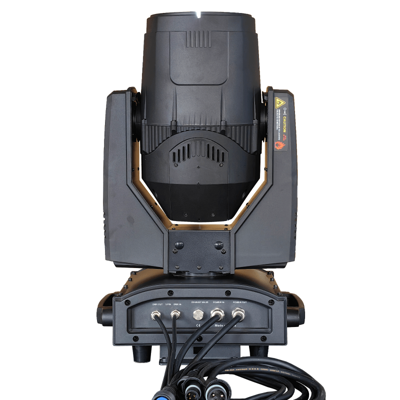
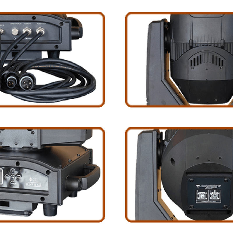
Use a cable conforming to specifications EIA RS-485: 2-pole twisted, shielded, 120Ohm characteristic impedance, 22-24 AWG, low capacity. Do not use microphone cable or other cable with characteristics differing from those specified. The end connections must be made using XLR type 3 or 5-pin male/female connectors. A terminating plug must be inserted into the last projector with a resistance of 120Ohm (minimum 1/4 W) between terminals 2 and 3.Figure 1 shows a signal line connection diagram (the fixture in the figure is an example picture and does not represent the real appearance of this product).
IMPORTANT: The wires must not make contact with each other or with the metal casing of the connectors. The casing itself must be connected to the shield braid and to pin 1 of the connectors.
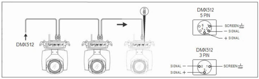
Figure 1 Diagram of the DMX Cable connection
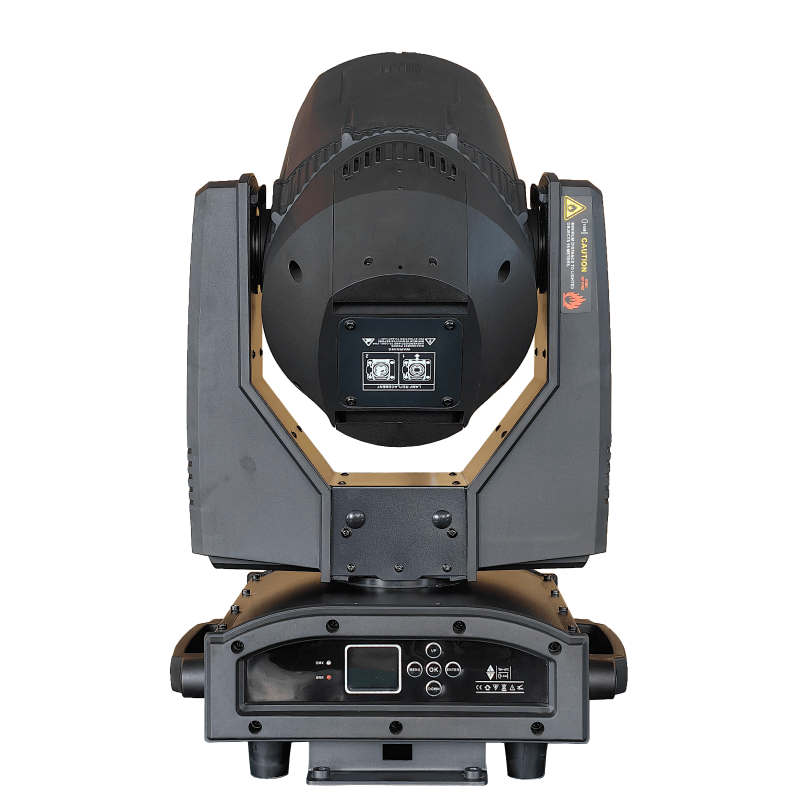
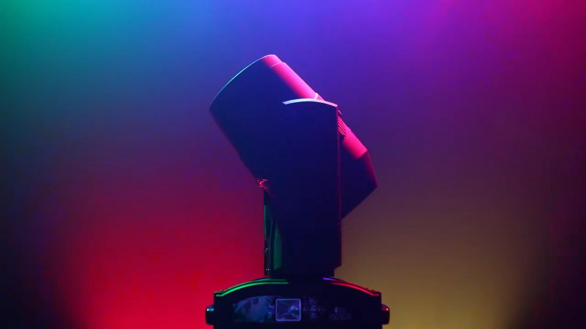
As shown in Figure 2 (the fixture in the figure is an example picture and does not represent the real appearance of this product),this equipment can be positioned and fixed by clamp in every direction of the stage. Locking system makes it easy to fasten to the bracket.
Attention! Two clamps is needed to fix the equipment. Every clamp is locked by fastener of 1/4 kind. Fastener can only be locked clockwise.
Attention! Fasten a safety string to the additional hole of side aluminum piece. The secondary accessory can not hang on the delivery handle. Nip the equipment on bracket.
RDM is an extended version of DMX512-A protocol. It is a remote device management protocol. Traditional DMX512 protocol communication is one-way communication. The protocol is based on RS-485 bus. RS-485 is a time-sharing multi-point, half-duplex protocol. Only one port is allowed to output at the same time. So, when using RDM, we should pay attention to it. The following points:
The diagram of the display panel show as Figure 3, above area is title for fixture description, the white font in the lower right corner shows the fault status of the fixture (when the fault information is not viewed, it displays "ERR", otherwise it displays "NOR"), and the status bar below shows the signal of the current fixture , fixture status, communication status, etc. (the panel in the figure is an example picture and does not represent the real appearance of the product panel,please select the panel of the same type as your product for reference.).
RDM protocol is embed in fixture, user set DMX address via cable using the controller support RDM function. when fixture was search by controller, displayer will echo ‘RDM’ indicate this RDM is work.
Note: Prevent damage the TFT displayer, Can not use sharp objects chick displayer.
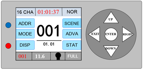
Figure 3-1 Diagram of the Five-buttons display panel
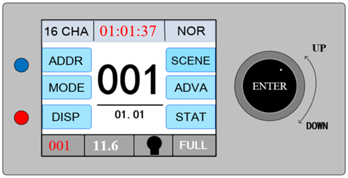
Figure 3-2 Diagram of the knob display panel
When the selected item is value need to been modified, the dialog shown in Figure 4 will popup.
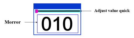
Figure 4 Dialog of value setting
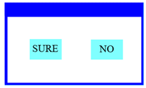
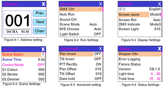
Figure 6 Diagram of the Parameter menu
Chick item of main menu, enter corresponding sub menu shown in Figure 6, In main menu, chick 1/6 function button into corresponding parameter menu.
Enter page show in Figure6-1, can set fixture DMX address, channel mode and so on.
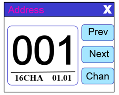
Figure 6-1
The menu settings of fixture have optimized the setting of addresses. Several settings of the address are as follows:
Provide one buttons:
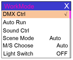
Figure 6-2
Through the page shown in Figure 6-2, the operating mode of the fixture can be set and the lamp can be controlled. The fixture supports four operating modes (DMX mode, auto mode, voice control mode and scene mode). Detailed parameter settings can be refer in the previous section. Specific parameter descriptions are as follows:
operating mode
DMX Ctrl |
DMX mode, receive DMX signal, RDM signal |
|
Auto Run |
Fixture run automatically according to built-in programs |
|
Sound Ctrl |
When the fixture detects a strong sound, the fixture automatically runs a scene according to the built-in program, otherwise it will stay the last scene |
|
Scene Mode 01 |
runs in a set scene, which supports most of the custom editing of 10 scenes. |
|
1~10 |
outputs the specified scene |
|
Auto |
Automatically loops the output scene in the set scene time (non-zero) order, and the scene with time 0 automatically ignore |
|
M/S Choose |
Master and slave selection, non-DMX mode takes effect, select the mode of data output, fixture detect DMX cable state automatic switch output, prevent data conflicts |
|
Master |
fixture runs built-in program. If DMX has no signal, it outputs data (synchronization), otherwise it does not output data. |
|
Slave |
fixture runs built-in program and do not output data |
|
Auto |
If DMX has no signal, the fixture will runs built-in program. Otherwise, the fixture will run in DMX Mode(follow DMX). |
|
Lamp switch |
(Lamp light source) pop-up confirmation dialog box, select "SURE" to confirm the current operation, turn on or off the lamp, switch time interval limited to 30 seconds |
|
Off |
the current lamp output is off |
|
On |
The current lamp output is turned on |
|
Scene mode applies to a single or a small number of fixture, just output a fixed scene, or need to run a simple program, you no need connect to the console, in the scene page can be edited.
If the light source is lamp, wait for 10 minutes before turning off the lamp.
Figure 6-3
The fixture support Chinese and English, invert display and so on. Enter the corresponding parameter settings as shown in Figure 6-3.The specific menu contents are as follows:
DISPLAY SETTING
Language |
display language settings |
|
English |
English display |
|
Chinese |
Chinese display |
|
Screen saver |
Set screen 30 seconds without operation, the screen's display content or method. |
|
OFF |
Keep the last operation page |
|
Mode1 |
Black |
|
Mode2 |
Black screen, showing the address code of the current fixture in the lower left corner. |
|
Mode3 |
Display trademark information, address code and operation mode. |
|
Mode4 |
Display trademark information, address code and operation mode,which lasts for 30 seconds ,black screen. |
|
Screen Rot |
Set the display direction of the screen. |
|
OFF |
No reverse display |
|
ON |
Reverse display |
|
DMX Indicate |
Set the indication mode of DMX signal indicator. |
|
Mode1 |
When signal is bright, no signal is off. |
|
Mode2 |
When signal is off, no signal is bright. |
|
Mode3 |
When signal is flash, no signal is off. |
|
Screen Light |
Set the screen backlight for 10 seconds without operation |
|
1~10 |
10 |
|
Enter the page shown in Figure 6-4(The channel shown in the picture is only an example of the function, please refer to the channel table description in the next section for the specific channel table of this product), and the fixture enters the scene editing mode. For example,under this page,when the [Control Mode] option is turned off ,the fixture does not receive DMX console data, and the edited data will effect on the fixture immediately.When it turned on, the console signal is received and the console data is read and reflected on the corresponding channel display.
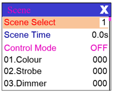
Figure 6-4
The content of the page depends on the currently selected channel mode, and the channel content and order displayed are consistent with the fixture channel table. Through this page, you can edit 10 scenes, as shown in the following table:
SCENE MODE
Scene Select |
Select the current operation scenario. |
|
1~10 |
The 10 scenes sets the format |
|
Scene Time |
Sets the retention time of the current scene when it is automatic,the final time is determined by the scene time multiplier, unit in 0.1 seconds. |
|
0 |
The current scene is not output in automatic scene output. |
|
1-255 |
0..1s-25.5s |
|
Control Mode |
Choose whether to use the console to manipulate the settings data |
|
OFF |
It is not possible to control the console and set the data directly from the current interface |
|
ON |
Using console control, the console data comes first when setting, and the setting is invalid in the current interface |
|
1. PAN |
0-255 |
Set up the data of each channel, and the contents and order of the display are one-to-one correspondence with the channel list of fixture. |
…… |
0-255 |
|
…… |
0-255 |
|
N. Function |
0-255 |
|
If the reset channel in the scene edits the effective reset data, the fixture will reset, but after reset, the corresponding reset channel value will automatically set 0, preventing multiple consecutive resets.
Looking at this page, you can get the current channel table slot of the fixture. For specific channel data, please refer to the detailed channel description.
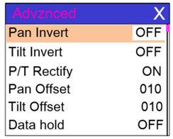
Figure 6-5
Enter the page shown in Figure 6-5, adjust the field parameters of fixture, facilitate the installation of fixture, etc.
ADVANCED SETTING
Pan Invert |
Set the rotation direction of PAN |
|
OFF |
|
|
ON |
|
|
Tilt Invert |
Set the rotation direction of TILT |
|
OFF |
|
|
ON |
|
|
P/T Rectify |
Setting up fixture to detect XY lost step and correct |
|
OFF |
Uncorrected position after out of step |
|
ON |
After losing step, the position is automatically corrected and the out of step fault is recorded. |
|
Pan Offset |
Setting the zero point of the PAN of the fixture |
|
4-150 |
||
Tilt Offset |
Setting the zero point of the TILT of the fixture |
|
4-48 |
||
Data hold |
When the fixture is not equipped with DMX signal, the output state of the fixture |
|
OFF |
No signal, so the motor and light source return to the position and state when reset is completed. |
|
NO |
No signal, keep the last frame DMX data output. |
|
|
Scene Time (multiple) |
Work with the scene time to determine the scene retention time |
|
1-255 |
Retention time = Scene time * multiple |
|
Lamp mode |
(lamp light source) Set the way to first open the lamp after power up |
|
Power on |
Turn on the lamp at power up and reset the lamp after 30 seconds. |
|
After reset |
Reset the fixture after 3 seconds when power-on, and turn on the lamp after reset. |
|
Manual |
After reset, manually turn on the lamp through the menu or console. |
|
Reset |
Pop up the confirmation box, select "SURE", and reset the fixture. |
|
Factory Setting |
Pop up the confirmation box, select "SURE", and return the lamp parameters to the factory settings. |
|
When choosing power-on mode, the lamp will wait for 30 seconds after power-on, let the lamp fully start, internal voltage is stable enough, then start the reset program, if the field capacity is stable, recommend power-on mode.
When the fixture can not calibrate the position, please check whether the "P/T Rectify" is turned off.
When the signal is unplugged, check the Data Hold setting first if the position of the fixture is not output as expected.
When setting the XY offset, after setting up, please control XY with the maximum stroke first to check that XY will not bump into the positioning rod or shell.
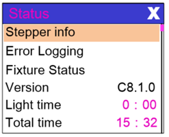
Figure 6-6
Entering the page shown in Figure 6-6, you can view the information and real-time status of the fixture to get their usage status. If the fixture need customer service, please provide the status information displayed on the page as a basis for judgment, as shown in the following table:
STATUS INFORMATION
Stepper info |
Display information status of all motors and signals in fixture. |
|
Hall |
No display, indicating that the motor has no Hall, 0 indicating that the motor leaves the correction position point, 1 indicating that the motor is in the correction position point |
|
Status |
Display motor reset status |
|
PAN |
Display real-time position value of PAN optocoupler feedback |
|
TILT |
Display real-time position value of TILT optocoupler feedback |
|
PAN OP |
Displays the PAN TILT optocoupler two signal level state, binary |
|
Error Logging |
Show the latest 8 error records when the fixture is reset and running. The error records are not saved after power failure. The current power cycle is valid. |
|
Error Logging |
Total number of failures detected after power on |
|
12::03 |
The time of power failure when the fault occurs is in minutes. |
|
Hall error |
The effective hall signal is not detected when the motor is reset |
|
Hall short |
When the motor is reset, the hall signal of the motor is always effective |
|
Opti error |
No effective optocoupler signal is detected when the motor is reset. |
|
Lose stop |
The corresponding motor is out of step during its operation. |
|
Hit |
Striking the positioning rod when the motor is reset |
|
Lamp error |
Lamp explosion accident |
|
NTC error |
The temperature sensor signal is abnormal |
|
Fan error |
The main fan is not working properly. |
|
Fixture status |
Displays the critical state data of the current fixture for reference. |
|
Communication prec |
0~100%, Communication quality of internal data link of lamps and lanterns |
|
Error Cnt |
The number of erroneous frames was detected after power on, and the total number of erroneous frames was detected. |
|
Light Temperature |
Show the temperature of the current light source, "---" means no detection. |
|
Panel Temperature |
Displays the temperature of the current display panel or the ambient temperature. |
|
Sensor1 Temperature |
Display the ambient temperature of the motherboard temperature or the motherboard installation position. |
|
Version |
Display the information and version of the current fixture, important reference for after sales maintenance. |
|
Device |
The name of the fixture is the same as the equipment information of RDM. |
|
Model |
The type of fixture is the same as the model information of RDM. |
|
Panel |
Firmware version and serial number of display panel |
|
Main Board |
Firmware version and serial number of mother board 1 |
|
Light time |
Record the total cumulative time of light source opening, unit minute, user manual cleaning, as a reference for regular maintenance of light source time. |
|
Total time |
The total accumulated time for recording the opening of fixture is not allowed to be removed. |
|
Note: the channel tables of different lamps are different. The following channel tables are for reference only
This luminance channel can be viewed in scene mode in order, channel mode is set in the "Address Settings" page, specific details of the data as follows:
CHANNEL TABLE
16 Channels Mode:
LIST-1 |
NAME |
VALUE |
BRIEF |
[ CH1 ] |
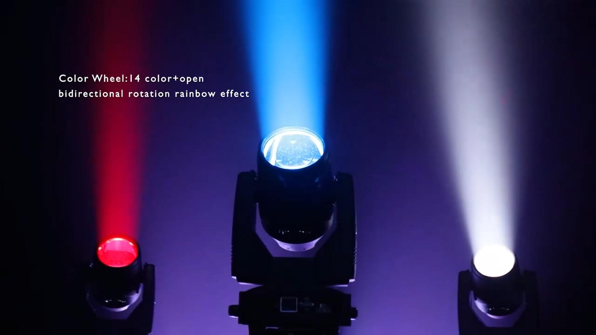
Colour |
0-3 |
White |
|
|
4-7 |
Colour1 |
|
|
8-11 |
Colour2 |
|
|
12-15 |
Colour3 |
|
|
16-19 |
Colour4 |
|
|
20-23 |
Colour5 |
|
|
24-27 |
Colour6 |
|
|
28-31 |
Colour7 |
|
|
32-35 |
Colour8 |
|
|
36-39 |
Colour9 |
|
|
40-43 |
Colour10 |
|
|
44-47 |
Colour11 |
|
|
48-51 |
Colour12 |
|
|
52-55 |
Colour13 |
|
|
56-59 |
Colour14 |
|
|
60-63 |
White+colour1 |
|
|
64-67 |
Colour1+Colour2 |
|
|
68-71 |
Colour2+Colour3 |
|
|
72-75 |
Colour3+Colour4 |
|
|
76-79 |
Colour4+Colour5 |
|
|
80-83 |
Colour5+Colour6 |
|
|
84-87 |
Colour6+Colour7 |
|
|
88-91 |
Colour7+Colour8 |
|
|
92-95 |
Colour8+Colour9 |
|
|
96-99 |
Colour9+Colour10 |
|
|
100-103 |
Colour10+Colour11 |
|
|
104-107 |
Colour11+Colour12 |
|
|
108-111 |
Colour12+Colour13 |
|
|
112-115 |
Colour13+Colour14 |
|
|
116-127 |
Colour14+White |
|
|
128-191 |
Rotate forward (fast to slow) |
|
|
192-255 |
Rotate reverse (slow to fast) |
[ CH2 ] |
Strobe |
0-3 |
Close |
|
|
4-103 |
Pulse strobe slow to fast |
|
|
104-107 |
Open |
|
|
108-207 |
Strobe slow to fast |
|
|
208-212 |
Open |
|
|
213-251 |
Random strobe slow to fast |
|
|
252-255 |
Open |
[ CH3 ] |
Dimmer |
0-255 |
0-100% dimmer |
[ CH4 ] |
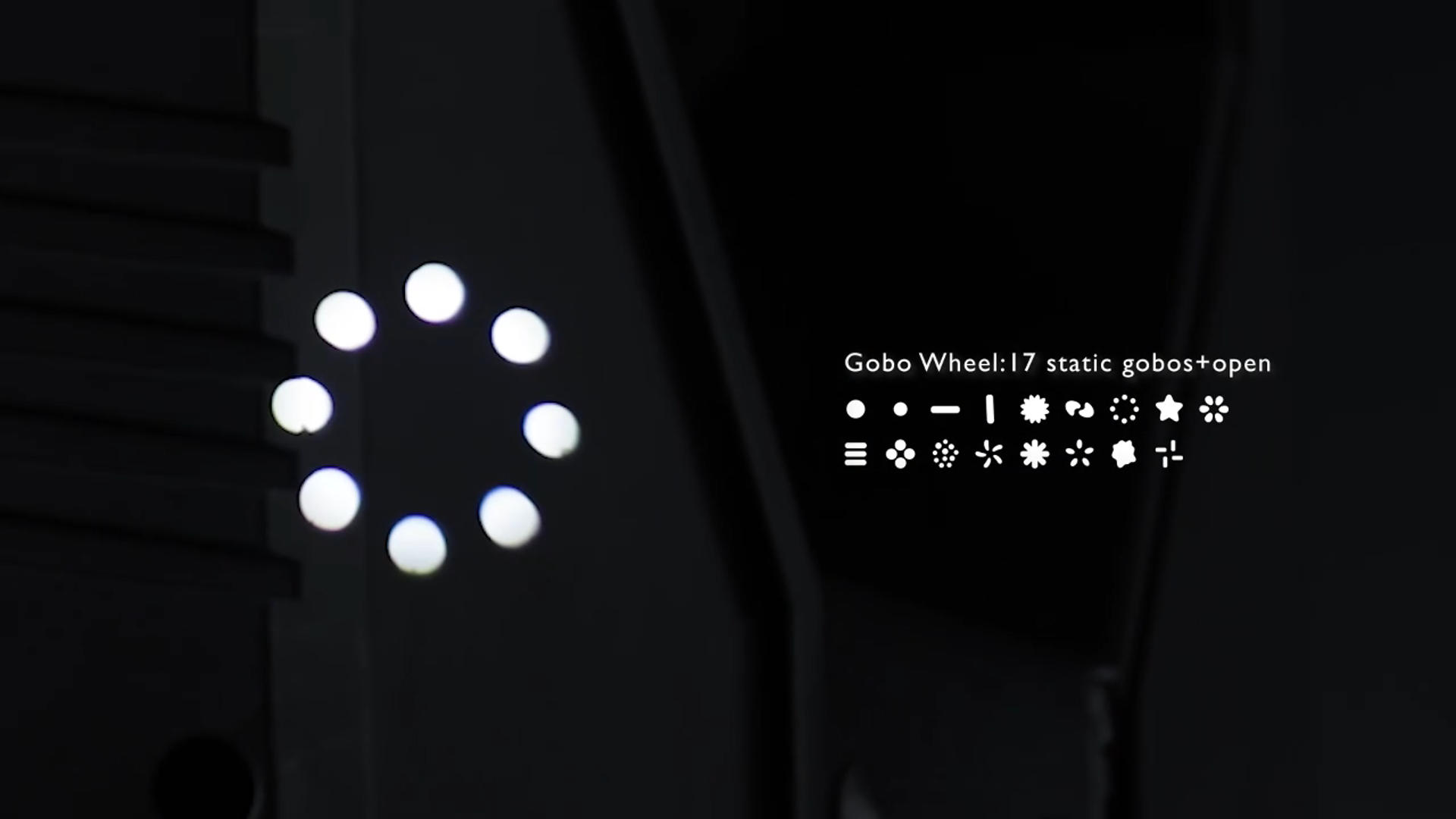
Gobo |
0-3 |
White |
|
|
4-7 |
Gobo1 |
|
|
8-11 |
Gobo2 |
|
|
12-15 |
Gobo3 |
|
|
16-19 |
Gobo4 |
|
|
20-23 |
Gobo5 |
|
|
24-27 |
Gobo6 |
|
|
28-31 |
Gobo7 |
|
|
32-35 |
Gobo8 |
|
|
36-39 |
Gobo9 |
|
|
40-43 |
Gobo10 |
|
|
44-47 |
Gobo11 |
|
|
48-51 |
Gobo12 |
|
|
52-55 |
Gobo13 |
|
|
56-59 |
Gobo14 |
|
|
60-63 |
Gobo15 |
|
|
64-67 |
Gobo16 |
|
|
68-71 |
Gobo17 |
|
|
72-113 |
Rotate reverse (fast to slow) |
|
|
114-117 |
Stop |
|
|
118-159 |
Rotate forward (slow to fast) |
|
|
160-166 |
Gobo1 shaking, slow to fast |
|
|
167-172 |
Gobo2 shaking, slow to fast |
|
|
173-179 |
Gobo3 shaking, slow to fast |
|
|
180-185 |
Gobo4 shaking, slow to fast |
|
|
186-191 |
Gobo5 shaking, slow to fast |
|
|
192-198 |
Gobo6 shaking, slow to fast |
|
|
199-204 |
Gobo7 shaking, slow to fast |
|
|
205-211 |
Gobo8 shaking, slow to fast |
|
|
212-217 |
Gobo9 shaking, slow to fast |
|
|
218-223 |
Gobo10 shaking, slow to fast |
|
|
224-230 |
Gobo11 shaking, slow to fast |
|
|
231-236 |
Gobo12 shaking, slow to fast |
|
|
237-243 |
Gobo13 shaking, slow to fast |
|
|
244-249 |
Gobo14 shaking, slow to fast |
|
|
250-255 |
Gobo15 shaking, slow to fast |
[ CH5 ] |
Prism1 |
0-31 |
None |
|
|
32-255 |
Inert prism1 |
[ CH6 ] |
Prism2.R |
0-127 |
0-360(degree) |
|
|
128-191 |
Rotate forward (slow to fast) |
|
|
192-255 |
Rotate reverse (slow to fast) |
[ CH7 ] |
Prism2 |
0-31 |
None |
|
|
32-255 |
Insert prism2 |
[ CH8 ] |
Prism2.R |
0-127 |
0-360(degree) |
|
|
128-191 |
Rotate forward (slow to fast) |
|
|
192-255 |
Rotate reverse (slow to fast) |
[ CH9 ] |
Focus |
0-255 |
Far to near |
[ CH10 ] |
Pan |
0-255 |
0-540(degree) |
[ CH11 ] |
Pan Fine |
0-255 |
0-2(degree) |
[ CH12 ] |
Tilt |
0-255 |
0-270(degree) |
[ CH13 ] |
Tilt Fine |
0-255 |
0-1(degree) |
[ CH14 ] |
PT Spd |
0-255 |
Fast to slow |
[ CH15 ] |
Frost |
0-127 |
None |
|
|
128-255 |
Insert frost |
[ CH16 ] |
Reset |
0-99 |
None |
|
|
100-105 |
Lamp off |
|
|
106-139 |
None |
|
|
140-145 |
Reset the effect motor after 3 seconds |
|
|
146-149 |
None |
|
|
150-199 |
Reset the Pan & Titl motor after 3 seconds |
|
|
200-205 |
Lamp on |
|
|
206-254 |
None |
|
|
255-255 |
Reset fxiture over 3 second |
AOPU AOPU 7*40W IP65 Bee Eye Moving Head Light RGBW Waterproof Moving Head Stage Light
AOPU RGBW Beam 6 Eye Bee Laser Light 6*15W LED Bee Eye Moving Head Beam Light for Sta Bar DJ Disco
5X40W RGBW 4-in-1 LED Finger Beam Stage Lights Sharpy Beam Series 5 Combination for DJ Aluminum Lamp Body
AOPU 24 X 20W RGBW 4in1 IP65 Architectural Wall Wash Light 600W LED City Outdoor Strobe Light Moving Head Lihgt for Building

Guangzhou Aopu Lighting Equipment Co., Ltd. offers a wide range of high-quality stage lighting products including LED lights, waterproof moving head lights, and more. Tailored solutions for theaters, concerts, and events.
3f-4f, No. 2 Building, Yongyi Road, Guangzhou, Guangdong, China
Copyright © 2026 Guangzhou Aopu Lighting Equipment Co., Ltd. All right reserved Privacy Policy